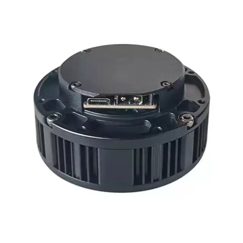
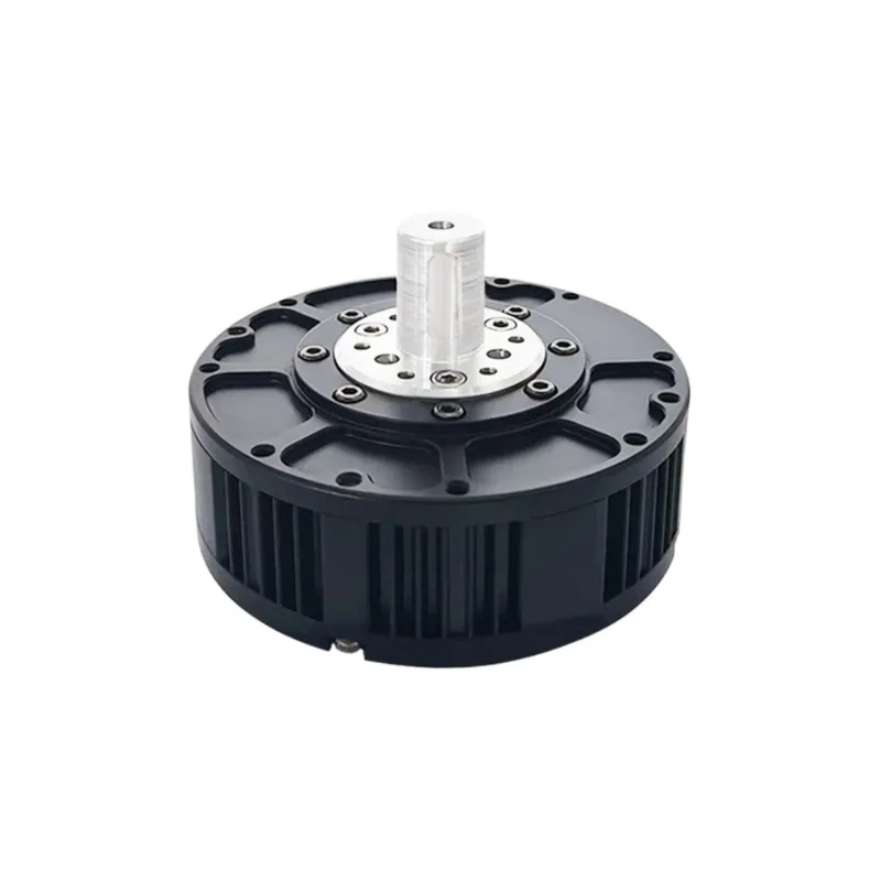
The GIM6010-8 joint motor, paired with the SDC104 driver board, is a high-performance solution. With a rated voltage of 24V and a wide voltage range of 12~56V, it offers flexibility in power supply. Boasting a rated power of 252W, a rated torque of 5N.M, and a peak torque of 11N.M, it delivers robust power. The planetary gear type with an 8:01 gear rate ensures reliable motion transmission, and the steel reducer gear material provides durability. Featuring a rated speed after reduction of 120 RPM and a max speed of 420 RPM, it can adapt to different motion requirements. With a low noise level of less than 60dB, it operates quietly. It supports CAN and Type-C communication, enabling seamless integration. The motor, with an IP54 protection grade, can work stably in temperatures from -20℃ to +80℃. It comes with a 16-bit resolution encoder on the driver, a second encoder on the output shaft, and supports custom brakes, making it an ideal choice for various applications like assisted rehabilitation robots, small robotic arms, and quadruped robots. Weighing 370g without the driver and 388g with it, its compact size (80*29.5mm without driver and 80*40mm with driver) allows for easy installation.
Mechanical Details
| Feature | Specification |
|---|
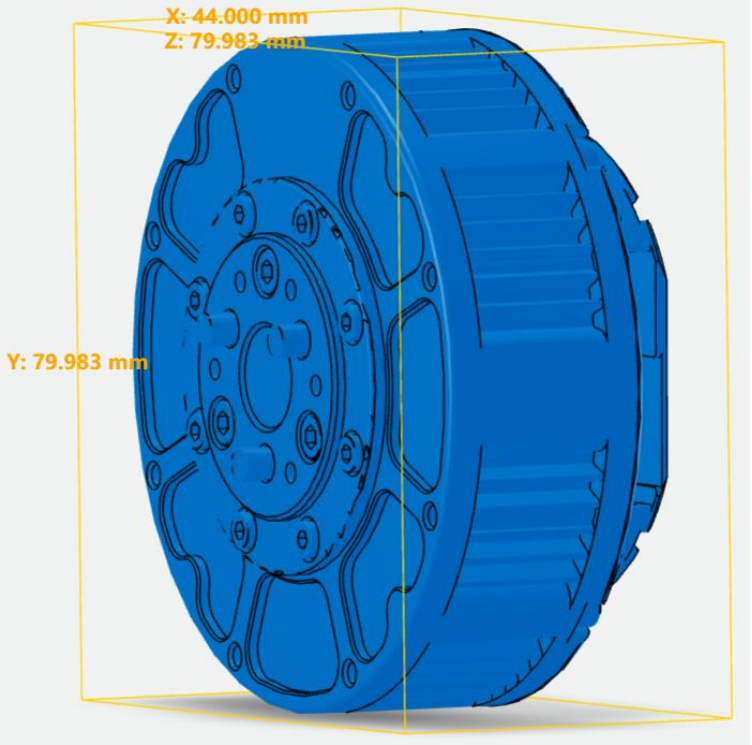
| Motor Size (no driver) | Ø80 × 29.5 mm |
| Motor Size (with driver) | Ø80 × 40 mm |
| Weight | 370g (motor only), 388g (w/ driver) |
| Noise Level | < 60 dB |
| Protection Rating | IP54 |
Gearbox & Load Ratings
| Specification | Value |
|---|
| Gear Ratio | 8:1 |
| Gear Type | Planetary (metal) |
| Backlash | ≤ 15 arcmin |
| Max Axial Load | 200 N |
| Max Radial Load | 800 N |
Communication & Control
| Feature | Detail |
|---|
| Communication | CAN (1Mbps) + USB Type-C (10Mbps) |
| Encoder | 16-bit Absolute Encoder (integrated) |
| Secondary Encoder Port | Supported |
| Brake (Comb Brake) | Supported |
| External Encoder | Not Supported |
Environment & Safety
| Feature | Specification |
|---|
| Motor Operating Temp | -20°C to +80°C |
| Driver Operating Temp | -20°C to +70°C |
| Over-temp Warning | Default at 90°C (adjustable) |
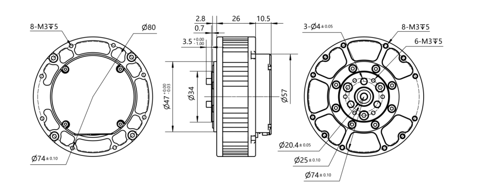
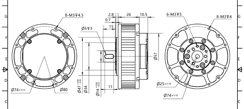
Motor Dimensions


Integrated Driver

| Parameter | Value |
|---|
| Voltage Range | 12V ~ 72V DC |
| Rated Output Current | 6A (Max line current: 30A) |
| Max Phase Current | 120A |
| Standby Power | < 10mA |
| Insulation Resistance | ≥ 100MΩ @ DC500V |
| Withstand Voltage | 600V AC for 1s, ≤ 2mA |
Feature
- Bionic Robotic Joint Motor: Mimics natural joint movements for enhanced flexibility.
- High Torque Output: Delivers powerful driving force for demanding tasks.
- Integrated Design: Combines motor, reducer, and control system in one compact unit.
- Built-in Sensors: Includes temperature and position sensors for real-time monitoring.
- High-Speed Communication: Enables fast and responsive control.
Applications:
- Assisted Rehabilitation Robotics: The GIM6010-8 suits these robots, providing precise, gentle movements for patient recovery. Its accuracy mimics natural joints, enhancing therapy.
- Small Robotic Arms: Ideal for high maneuverability and precision needs. It powers complex tasks in micro-manufacturing, assembly, and labs.
- Industrial Quadruped Robots: In complex industrial areas, the GIM6010-8’s robust design and reliability enable robots to navigate uneven grounds, inspect, and work efficiently. –
- Smart Home Automation: Can be integrated into home robots for chores or assisting the elderly and disabled. Its compact size and control are suitable. –
- Educational and Experimental Platforms: Great for institutions and research. Students and researchers can explore robotics, develop algorithms, and experiment due to its accessible interface and features.
User's Manual
Drive Information
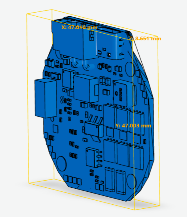
1. Appearance and 3D dimensions
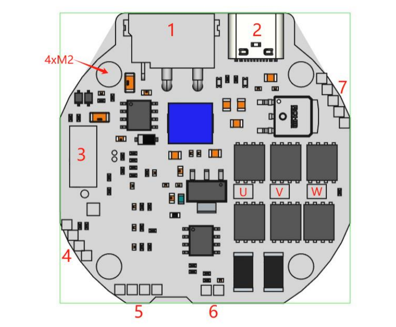
2. Interface Overview

Interface Definitions
| No. | Interface Name / Definition |
|---|
| 1 | 15–60V Power Supply & CAN Communication Integrated Terminal |
| 2 | Type-C Debugging & Host Computer Communication Interface |
| 3 | Expansion Slot (supports RS485, EtherCAT, PWM, Pulse-Direction, Throttle control, etc.) |
| 4 | SWD Debugging & Firmware Download Interface |
| 5 | Secondary Encoder Interface (Supports I2C & UART) |
| 6 | Motor Temperature Interface (NTC Sensor) |
| 7 | Brake/Brake Resistor Interface, 12V Power Output, Min/Max Limit Switch Interface |
| 8 | U/V/W Phase Winding Solder Pads |
| 9 | Mounting Holes (4 × M2 screws) |
3. Interface Detailed Definition
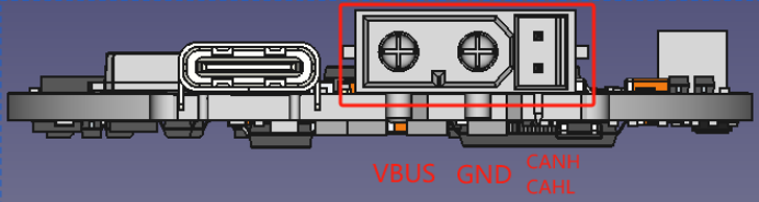
Power supply and CAN communication/RS485/PWM terminals

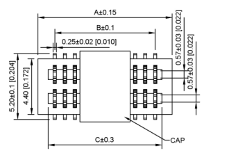
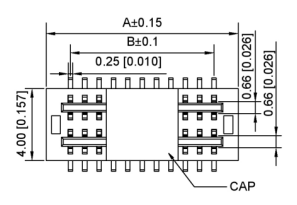
The onboard terminal model is XT30PB(2+2)-M, and the mating cable-end connector is XT30(2+2)-F, both manufactured by AMASS.
In PWM mode, the CANH pin functions as the PWM signal input.
In pulse mode,
Note: In versions that support RS485, the CANH and CANL pins also serve as the RS485 A/B differential signal lines.
4. Type-C Debug Interface
The Type-C port uses a standard data cable specification and is compatible with commonly used Type-C cables from PCs or smartphones.
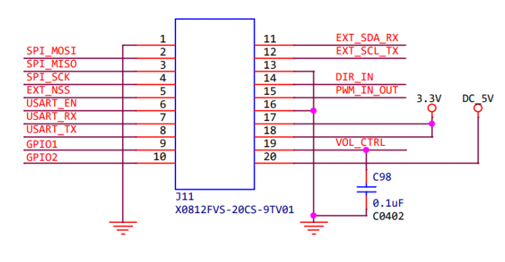
5. Expansion Slot Interface
This slot is designed to provide a variety of inter-board expansion interfaces, allowing third-party developers to design custom expansion boards.
Note: This expansion interface is no longer available starting from hardware version 3.9 and later.

Third-party developers can interact with the driver via various interfaces such as SPI, USART, I2C, PWM, ADC, and GPIO, enabling a wide range of custom expansion features.


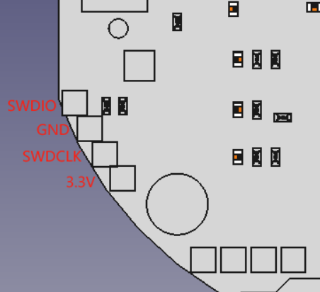
6. SWD Debug Interface
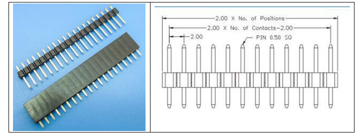
The SWD interface consists of 2 mm pitch through-holes. Users can solder a 2 mm single-row pin header for debugging purposes, as shown in the figure below:


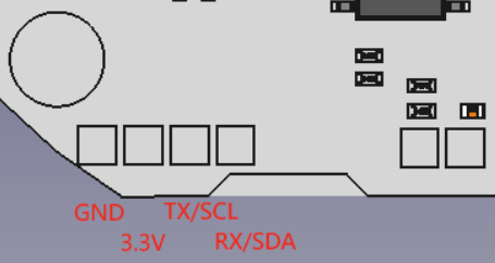
7. Secondary Encoder Interface
This interface uses 2 mm pitch through-holes. Users may solder a 2 mm single-row pin header, as described in the previous section.
It supports communication with a secondary encoder via USART (TX/RX) or I2C (SCL/SDA).

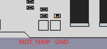
8. Motor Temperature Interface
The motor includes a built-in 10 kΩ NTC thermistor.
Two wires from the thermistor should be soldered to the MOT_TEMP and GND pads.
There is no polarity requirement for the wiring.

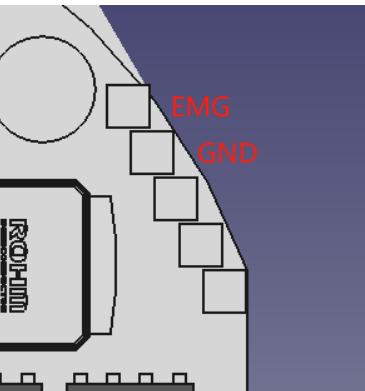
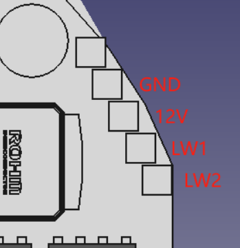
9. Brake / Braking Resistor Interface
The upper two solder pads in the pin header area are reserved for the brake or braking resistor interface, using 2 mm pitch holes. Users may solder a 2 mm single-row pin header as needed.
When used as a brake (holding brake) interface:
The driver outputs a continuous current to this interface upon power-up to release the brake, allowing the motor to rotate freely.
If the driver loses power, the output current stops, the brake engages, and the motor will lock at its current position.
When used as a braking resistor interface:
An external braking resistor (also known as a dump resistor) can be connected to this interface.
When the back electromotive force (EMF) exceeds the threshold voltage, the braking resistor will dissipate the energy to prevent failure of emergency braking or potential damage to the driver from overvoltage.

10. Limit Switch Interface
The driver provides two limit switch interfaces, along with a 12V power supply for external limit switches. The interface consists of 2 mm pitch pin holes, and users may solder a 2 mm single-row pin header as needed.
Both 2-wire switches and 3-wire NPN switches are supported for external connection.

Main Components and Specifications
| No. | Component | Model/Specification | Quantity |
|---|
| 1 | MCU | N32G455 | 2 |
| 2 | Driver Chip | FD6288O | 1 |
| 3 | Magnetic Encoder Chip | MA732, 14-bit absolute | 1 |
| 4 | MOSFET | JMSH1004NG, 100V / 120A | 1 |
Exception Table
System Exceptions
| Error Code | Description |
|---|
| 0x00000002 | DC BUS UNDER_VOLTAGE |
| 0x00000004 | DC BUS OVER_VOLTAGE |
| 0x00000008 | DC BUS OVER_REGEN_CURRENT |
| 0x00000010 | DC BUS OVER_CURRENT |
Drive Exceptions
| Error Code | Description |
|---|
| 0x00000001 | INVALID STATE |
| 0x00000040 | MOTOR FAILED |
| 0x00000100 | ENCODER FAILED |
| 0x00000200 | CONTROLLER FAILED |
| 0x00001000 | MIN ENDSTOP PRESSED |
| 0x00002000 | MAX ENDSTOP PRESSED |
| 0x00004000 | ESTOP REQUESTED |
| 0x00020000 | HOMING WITHOUT ENDSTOP |
| 0x00080000 | UNKNOWN POSITION |
Motor Abnormal
| Hex Code | Error Name | Description (English Translation) |
|---|
| 0x00000001 | PHASE_RESISTANCE_OUT_OF_RANGE | Phase resistance out of normal range |
| 0x00000002 | PHASE_INDUCTANCE_OUT_OF_RANGE | Phase inductance out of normal range |
| 0x00000004 | CONTROL_DEADLINE_MISSED | FOC deadline missed |
| 0x00000008 | MODULATION_MAGNITUDE | SVM modulation abnormal |
| 0x00000010 | CURRENT_SENSE_SATURATION | Phase current saturation |
| 0x00000020 | CURRENT_LIMIT_VIOLATION | Motor current too high |
| 0x00000040 | MOTOR_THERMISTOR_OVER_TEMP | Motor temperature too high |
| 0x00000080 | FET_THERMISTOR_OVER_TEMP | Module temperature too high |
| 0x00000100 | TIMER_UPDATE_MISSED | FOC processing not timely |
| 0x00000200 | CURRENT_MEASUREMENT_UNAVAILABLE | Phase current sample lost |
| 0x00000400 | CONTROLLER_FAILED | Controller failure |
| 0x00000800 | I_BUS_OUT_OF_RANGE | Bus current abnormal |
| 0x00001000 | BRAKE_RESISTOR_DISARMED | Brake resistor function abnormal |
| 0x00002000 | SYSTEM_LEVEL | System-level error |
| 0x00004000 | BAD_TIMING | Phase current sampling not in time |
| 0x00008000 | UNKNOWN_PHASE_ESTIMATE | Phase estimation unknown |
| 0x00010000 | UNKNOWN_PHASE_VEL | Phase velocity unknown |
| 0x00020000 | UNKNOWN_TORQUE | Torque unknown |
| 0x00040000 | UNKNOWN_CURRENT_COMMAND | Current command unknown |
| 0x00080000 | UNKNOWN_CURRENT_MEASUREMENT | Current measurement unknown |
| 0x00100000 | UNKNOWN_BUS_VOLTAGE | Bus voltage unknown |
| 0x00200000 | UNKNOWN_VOLTAGE_COMMAND | Voltage command unknown |
| 0x00400000 | UNKNOWN_GAINS | Gain parameters unknown |
| 0x00800000 | CONTROLLER_INITIALIZING | Controller initializing |
| 0x01000000 | UNBALANCED_PHASES | Phase current imbalance |
Control Exceptions
| Error Code | English Description |
|---|
| 0x00000001 | OVERSPEED |
| 0x00000002 | INVALID INPUT MODE |
| 0x00000004 | UNSTABLE GAIN |
| 0x00000020 | INVALID ESTIMATE |
| 0x00000080 | SPINOUT DETECTED |
Encoder Exceptions
| Error Code | English Description |
|---|
| 0x00000001 | UNSTABLE GAIN |
| 0x00000002 | CPR_POLEPAIR MISMATCH |
| 0x00000004 | NO RESPONSE |
| 0x00000400 | SECONDARY ENCODER COMMUNICATION FAIL |

Reviews
There are no reviews yet.