
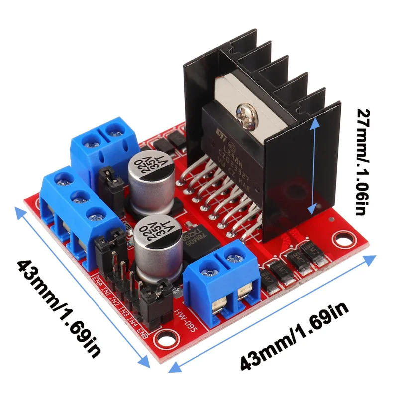
This module employs the L298N as the main driver chip, known for its strong driving capability, low heat generation, and robust anti-interference performance. The L298N chip features a 15-pin package and offers excellent performance for motor control applications. Below are its main features, explained in detail:
Key Features
- High Operating Voltage
- The module supports operating voltages of up to 46V, making it suitable for a wide range of applications requiring higher voltage levels.
- High Output Current
- It delivers a peak current of 3A for short durations and continuous current of 2A, ensuring stable and reliable operation for high-power motors.
- Rated Power
- The rated power output of the chip is 25W, allowing it to handle demanding loads efficiently.
- Integrated Dual H-Bridge Driver
- The chip includes two H-bridge drivers, making it capable of controlling:
- DC motors
- Stepper motors (two-phase or four-phase)
- Relay coils and other inductive loads
- The chip includes two H-bridge drivers, making it capable of controlling:
- Logic Control
- Operates using standard logic level signals for simple and seamless control.
- Equipped with two enable control pins, which allow the device to start or stop without being affected by input signals.
- Low Voltage Logic Circuit Support
- Features a dedicated logic power input to enable the internal circuit to function efficiently at low voltage.
- External Feedback Capability
- Supports the connection of an external detection resistor to provide real-time feedback to the control circuit, enhancing accuracy and stability in motor operations.
Additional Advantages
- Built-in Power Supply Options
- The module integrates a 78M05 voltage regulator that can draw power directly from the driver supply.
- Important Note: When using a driver voltage greater than 12V, it is recommended to supply an external 5V logic power source to avoid potential damage to the regulator.
- Enhanced Reliability
- Equipped with large-capacity filter capacitors and flyback protection diodes, the module minimizes electrical noise and improves overall reliability during operation.
Applications
This versatile motor driver module is well-suited for controlling various motorized systems, such as:
- Robotics and automation systems
- Stepper motor-based CNC machines
- DC motor-powered vehicles
- Relay-driven industrial equipment
Video
Learn
Standard Application (Operating Voltage: 7V to 12V)
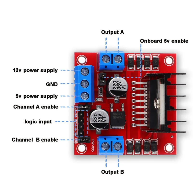
- When the driving voltage (marked as VCC input on the board) is in the range of 7V-12V, the onboard 78M05 voltage regulator provides logic power to the L298N chip.
- Steps:
- Connect the driving power supply to the VCC motor driving terminal.
- Press the onboard 5V enable button. The indicator light will turn on, signifying that the logic power is supplied internally.
- In this mode, there is no need for an external logic power supply. The +5V terminal on the board can output 5V to external devices but must not be connected to an external power source.
This configuration is suitable for conventional applications where the driving voltage falls within the 7V-12V range.
High-Voltage Application (Driving Voltage: 12V-24V)
- For driving voltages exceeding 12V (up to 24V), the onboard 78M05 regulator is not used.
- Steps:
- Disable the onboard 5V regulator by releasing the 5V enable button. The indicator light will turn off.
- Connect an external 5V power supply to the 5V output terminal to power the L298N’s logic circuitry.
Note: While the L298N datasheet specifies a maximum driving voltage of 35V, practical experience suggests a safe upper limit of 24V to ensure stable operation.
This configuration is suitable for high-voltage driving scenarios, such as powering motors with a rated voltage of 18V.
5V Enable Signal
- The 5V enable signal is a control signal (high level: 5V).
- When the signal is active, and the motor driver module is correctly powered, the module outputs current to the motor.
- If the signal is inactive, no current flows to the motor even if the power supply is connected.
PWM Speed Control and Motor Direction
- The ENA and ENB pins are the enable pins for the motor channels, and they support PWM input for speed control:
- To use PWM for speed adjustment, remove the default jumper caps connecting the ENA/ENB pins to VCC.
- Connect the ENA and ENB pins to external PWM signals.
- The IN1, IN2, IN3, IN4 pins are used to control motor rotation direction:
- IN1 and IN2 control Motor A.
- IN3 and IN4 control Motor B.
- Setting the pins to high and low levels determines the motor’s forward, reverse, or stop states.
Reviews
There are no reviews yet.