


The ESP32-S3-DevKitM-1 is an entry-level development board equipped with either ESP32-S3-MINI-1 or ESP32-S3-MINI-1U, a module named for its small size. This board integrates complete Wi-Fi and Bluetooth® Low Energy functions.
Most of the I/O pins on the module are broken out to the pin headers on both sides of this board for easy interfacing. Developers can either connect peripherals with jumper wires or mount ESP32-S3-DevKitM-1 on a breadboard.
Description of Components
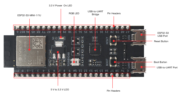
The key components of the board are described in a counter-clockwise direction, starting from the ESP32-S3-MINI-1/1U module.
| Key Component | Description |
|---|---|
| ESP32-S3-MINI-1/1U | ESP32-S3-MINI-1 and ESP32-S3-MINI-1U are two general-purpose Wi-Fi and Bluetooth Low Energy combo modules that have a rich set of peripherals. ESP32-S3-MINI-1 comes with a PCB antenna. ESP32-S3-MINI-1U comes with an external antenna connector. At the core of the modules is ESP32-S3FN8, a chip equipped with an 8 MB flash. Since flash is packaged in the chip, rather than integrated into the module, ESP32-S3-MINI-1/1U has a smaller package size. |
| 5 V to 3.3 V LDO | Power regulator that converts a 5 V supply into a 3.3 V output. |
| Pin Headers | All available GPIO pins (except for the SPI bus for flash) are broken out to the pin headers on the board for easy interfacing and programming. For details, please see Header Block. |
| USB-to-UART Port | A Micro-USB port used for power supply to the board, for flashing applications to the chip, as well as for communication with the chip via the on-board USB-to-UART bridge. |
| Boot Button | Download button. Holding down Boot and then pressing Reset initiates Firmware Download mode for downloading firmware through the serial port. |
| Reset Button | Press this button to restart ESP32-S3. |
| ESP32-S3 USB Port | ESP32-S3 full-speed USB OTG interface, compliant with the USB 1.1 specification. The interface is used for power supply to the board, for flashing applications to the chip, for communication with the chip using USB 1.1 protocols, as well as for JTAG debugging. |
| USB-to-UART Bridge | Single USB-to-UART bridge chip provides transfer rates up to 3 Mbps. |
| RGB LED | Addressable RGB LED, driven by GPIO48. |
| 3.3 V Power On LED | Turns on when the USB power is connected to the board. |
Key Features
- ESP32-S3-MINI-1 Module: Powered by a dual-core Tensilica LX7 processor with a clock speed of up to 240 MHz, providing excellent processing power for edge computing applications.
- Wi-Fi and Bluetooth 5 (LE): Built-in 2.4 GHz Wi-Fi and Bluetooth 5 (LE) dual-mode wireless communication, perfect for IoT devices requiring wireless connectivity.
- Rich GPIO Pins: Offers multiple GPIO pins supporting interfaces like UART, SPI, I2C, I2S, PWM, and ADC, making it easy to connect external devices.
- USB Type-C Interface: The board includes a USB Type-C port for power, firmware download, and debugging, and supports USB OTG.
- Low Power Design: Supports various low-power modes, including deep sleep, making it suitable for battery-powered applications.
- AI Accelerator: The ESP32-S3 features a built-in AI vector accelerator optimized for convolutional neural networks (CNN), enhancing AI processing capabilities for edge devices.
- Large Storage Capacity: Onboard 512KB SRAM and 384KB ROM, support for external PSRAM (up to 8MB), and 4MB of Flash, suitable for complex applications.
- Development Environment Support: Fully compatible with the ESP-IDF (Espressif IoT Development Framework), and supports various third-party development environments such as Arduino and PlatformIO.
- Security Features: Includes a hardware encryption engine that supports AES, SHA, and RSA algorithms, making it ideal for IoT applications with high security requirements.
- Compact Size: The development board’s compact form factor makes it easy to integrate into various devices.
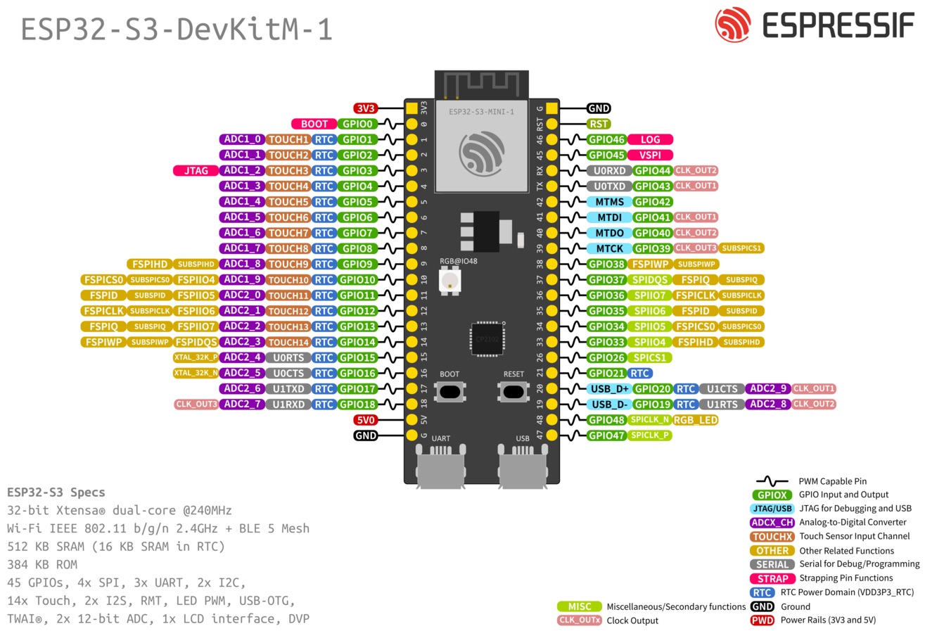
Pin Layout
Applications
- Smart home devices
- Wearable technology
- Smart agriculture
- Industrial automation
- Voice recognition and AI edge computing
- Wireless sensor networks
Reviews
There are no reviews yet.