
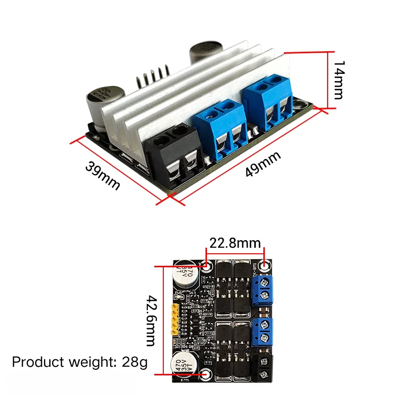
This dual H-bridge motor driver module is designed for versatile applications, capable of driving two DC motors or one 4-wire bipolar stepper motor. It supports a wide operating voltage range of 3V to 18V for both power and control signals, making it compatible with various systems. With a single-channel working current of 10A (15A peak), it is suitable for high-performance scenarios, and additional heat dissipation is recommended for currents above 8A. The module supports PWM frequency up to 2kHz with a duty cycle range of 0-100%, ensuring precise speed and torque control. Compact in size at 49mm x 39mm x 14mm and weighing only 28g, it is easy to integrate into your projects. Packaged in an anti-static bag, this module is perfect for robotics, automation, and experimental setups.
Motor Driver Logic Truth Table
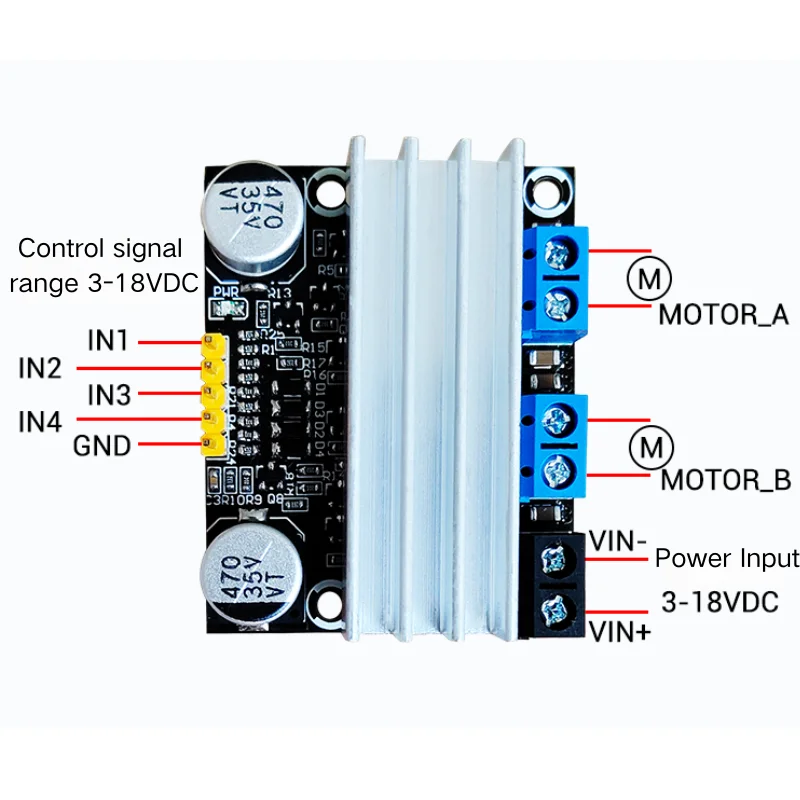
IN1, IN2, IN3, and IN4 are connected to the microcontroller’s IO ports or other signal sources, while MOTOR_A and MOTOR_B are connected to the motors.
| Motor | Motor Status | IN1 | IN2 | IN3 | IN4 |
| MOTOR_A | Forward (PWM) | 1/PWM | 0 | ||
| Reverse (PWM) | 0 | 1/PWM | |||
| Stop | 0 | 0 | |||
| Brake | 1 | 1 | |||
| MOTOR_B | Forward (PWM) | 1/PWM | 0 | ||
| Reverse (PWM) | 0 | 1/PWM | |||
| Stop | 0 | 0 | |||
| Brake | 1 | 1 |
Note:
- 1 represents a high level, 0 represents a low level, and PWM refers to a pulse width modulation signal used to adjust speed by changing the duty cycle.
- Supports a wide signal range of 3-18V. If no signal is connected, the default input is 0.
Precautions
- Stop Before Changing Direction
- When reversing the motor, ensure the motor stops or brakes first. A delay of over 0.5 seconds is recommended to prevent potential damage caused by high instantaneous current during direction switching.
- Avoid Reverse Polarity
- Do not reverse the power supply’s positive and negative terminals, as this will damage the module. Also, avoid connecting the power supply directly to the motor interface.
- Frequency Recommendations
- For optimal efficiency, a PWM frequency of 400Hz is suitable for small DC motors. The maximum recommended frequency is within 2kHz. Higher frequencies can cause the module to overheat.
Key Features
- Dual Independent Motor Control
- Supports two independent motor channels, with each channel capable of delivering a continuous current of 10A and a peak current of 15A.
- Wide Power Supply Range
- Operates on a wide voltage range of 3-18V for both motor power and control signal. Compatible with 3.3V and 5V logic levels.
- High-Performance MOSFETs
- Utilizes low-voltage, low-resistance MOSFETs, allowing for high current output even at low voltages. Ideal for model racing and competitive applications.
- Dual Independent Motor Control
Reviews
There are no reviews yet.