How to Use the DMBOTs DM-J4340-2EC Robotic Actuator Motor – Modes & Quick Start

introducing the DMBOTs DM-J4340-2EC Robotic Actuator Motor — a compact yet powerful joint motor commonly used in robotic arms, service robots, and mobile robot platforms.
In robots and automation equipment, a joint motor works just like the muscle inside a joint. Today, we’re introducing the DMBOTs DM-J4340-2EC Robotic Actuator Motor — a compact yet powerful joint motor commonly used in robotic arms, service robots, and mobile robot platforms.
Although it is small in size, with only 57 mm diameter and 362 g weight, it can deliver an impressive 9 Nm rated torque and up to 27 Nm peak torque. This makes it a great choice for applications where space is limited but high power is required.
Now, let’s walk through its operating modes and how to get started, explained step by step in simple language.

DM-J4340-2EC Robotic Actuator Motor Specifications

Parameter CategoryDM-J4340-2EC (24V)DM-J4340-2EC (48V)
Rated Torque9 Nm9 Nm
Peak Torque27 Nm27 Nm
No-Load Max Speed52 rpm100 rpm
Rated Current2.5 A2.5 A
Peak Current8 A8 A
Outer Diameter57 mm57 mm
Height53.3 mm53.3 mm
Weight~362 g~362 g
EncoderDual 14-bit magnetic encoderDual 14-bit magnetic encoder

What These Parameters Mean

  • 9 Nm Torque: Enough to easily drive a 5–10 kg robotic arm joint.
  • 27 Nm Peak Torque: Can handle short bursts of ‘heavy-duty’ operations, like lifting a relatively heavy load.
  • Dual 14-bit Encoder: Provides very high positioning accuracy, so the motor moves smoothly with almost no ‘shaking’ during motion.

Three Operating Modes – Like Switching ‘Driving Styles’

he DMBOTs DM-J4340-2EC Robotic Actuator Motor supports three common modes, which you can think of as different driving styles for the motor.
  1. MIT Mode – ‘Smart Driving’

In MIT Mode, the motor follows the original MIT control logic, allowing you to flexibly set limits for position, velocity, and torque.
The MIT Mode of the DMBOTs DM-J4340-2EC Robotic Actuator Motor is specially designed to be compatible with the original MIT control logic. This means you can switch to it seamlessly and still flexibly set control limits, including P_MAX (position limit), V_MAX (velocity limit), and T_MAX (torque limit).
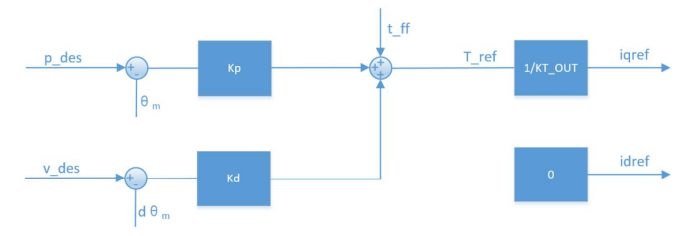
How it works under the hood: The motor driver takes the incoming CAN bus data (control commands), translates it into control variables, and then calculates the torque value. This torque is passed to the current loop, which regulates the motor’s phase current so that the actual output torque matches your target. 👉 In short: You give high-level commands → driver converts → current loop executes → motor produces the desired torque.
Here’s a simple control block diagram for MIT Mode:

Example Cases

Case 1: Constant Speed
If you want the motor to spin at a steady speed, set kp = 0 (ignore position), keep kd ≠ 0, and give a target speed v_des.

p_des = 0.0; // Position not controlled
v_des = 20.0; // Target speed = 20 rad/s
kp = 0.0; // Disable position loop
kd = 1.0; // Speed loop gain
t_ff = 0.0; // No feedforward torque

👉 The motor will rotate like a fan at constant speed.
Case 2: Constant Torque Output If you want the motor to just push with constant torque (like applying steady force), set both kp = 0 and kd = 0, then directly assign torque via t_ff.

// MIT Mode Example Command
p_des = 0.0;
v_des = 0.0;
kp = 0.0;
kd = 0.0;
t_ff = 2.0; // Apply 2 Nm torque

👉 The motor will act like a spring pulling with steady force.
Important Safety Tip: If you are controlling position but accidentally set kd = 0, the system may oscillate or even go unstable. It’s like driving a car downhill with broken brakes — risky and unsafe. Always keep a proper damping gain!
  1. Position-Velocity (Cascaded Position) Mode — imilar to ‘Autonomous Navigation’

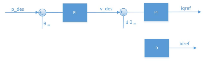
Position-Cascaded Mode uses a three-loop cascade control, where:
  • The outer loop is the position loop, whose output serves as the setpoint for the velocity loop.
  • The velocity loop output serves as the setpoint for the inner current loop, which controls the actual current output. The control block diagram is as follows:
  • p_des is the target position for control.
  • v_des is used to limit the maximum absolute speed during motion.
Example: Suppose you want the motor to move to 90° (p_des = 1.57 rad), but you want to limit its speed. You can set a maximum speed v_des. The motor will then reach the target smoothly following the sequence: accelerate → constant speed → decelerate.
The control block diagram is shown below:
Practical Case: Move the motor to 90° (1.57 rad) while limiting the maximum speed to 5 rad/s:

// Position-Velocity Mode Command Example
p_des = 1.57; // Target angle 90°
v_des = 5.0; // Maximum speed 5 rad/s
kp = 50.0; // Position loop gain
kd = 1.0; // Velocity loop damping
t_ff = 0.0; // No additional torque feedforward

👉 The motor will first accelerate, then decelerate smoothly, stopping precisely at 90°.
Advantages:
  • High precision
  • Smooth motion
  • Suitable for robot joint movements, e.g., slow grasping with a robotic arm
Disadvantages:
  • Slightly slower response
  • Not suitable for scenarios requiring ‘lightning-fast’ movements
Additional Notes:
  • When using the recommended parameters from the debugging assistant, good control accuracy can be achieved and the motion remains relatively smooth, though the response time is longer.
  • Besides v_des, you can also configure acceleration and deceleration values. Increasing them may reduce oscillations during motion.
  • Units: p_des in rad, v_des in rad/s, data type: float.
  • The damping factor must be a positive number greater than 0. For reference, see the notes for Velocity Mode.
  1. Velocity Mode — Similar to ‘Cruise Control’

Velocity Mode is used to make the motor run at a constant speed.
  • For example, if you want a wheeled robot to move continuously at 50 rad/s, you can simply set v_des = 50, and the motor will maintain that speed steadily.
The control block diagram is shown below:
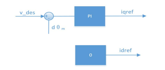
Practical Case: Keep the motor running at 50 rad/s:

// Velocity Mode Command Example
p_des = 0.0; // Position is not controlled
v_des = 50.0; // Constant speed 50 rad/s
kp = 0.0; // No position loop control
kd = 4.0; // Damping factor, recommended value
t_ff = 0.0; // No additional torque feedforward

Tip:
  • The damping factor kd should be set between 2.0 and 10.0, with 4.0 recommended.
  • If too small, the motor will oscillate.
  • If too large, the motion will feel sluggish.
Notes:
  • v_des unit is rad/s, data type float.
  • When using the debugging assistant to automatically calculate parameters, the damping factor must be a positive number greater than 0.
  • A too-small damping factor may cause speed oscillation and overshoot, while a too-large damping factor may increase rise time. The recommended value is 4.0.
Advantages:
  • Maintains a stable, constant speed
  • Simple and effective for tasks like wheeled robot motion
Control Block Diagram: Velocity Mode allows the motor to run steadily at the set speed; the control block diagram is shown below.

How to ‘Talk’ to the Motor: CAN Communication

The DMBOTs DM-J4340-2EC robotic actuator communicates with the controller via CAN bus at a fixed baud rate of 1 Mbps. You can think of this as the ‘language’ between the motor and the controller. Commands are sent and status is received in real time.
CAN frames are divided into two types:
  • Receive Frames: Control data sent to the motor, e.g., ‘move to 90°’ or ‘maintain 50 rad/s speed.’
  • Feedback Frames: Status data sent by the motor back to the controller, e.g., ‘I’m at 45°, my speed is 20 rad/s, temperature is 60°C.’
⚠ Note: The receive frame format and frame ID differ depending on the selected mode, but the feedback frame is the same for all modes.

Feedback Frame

The feedback frame reports the motor’s current state and includes:
  • Position (POS): Current motor angle
  • Velocity (VEL): Current speed
  • Torque (T): Current output torque
  • MOS Temperature (T_MOS): Average temperature of the MOSFETs on the driver
  • Rotor Temperature (T_Rotor): Average temperature of the motor coils
  • Error Code (ERR): Status like overcurrent, overvoltage, overtemperature
Example: If the motor overheats, it will return error code B (MOS over-temperature). You will know how to provide cooling to prevent damage.
Feedback Frame Format (8 bytes):
feedback messageD[0]D[1]D[2]D[3]D[4]D[5]D[6]D[7]
MST_IDID|ERR<<4POS[15:8]POS[7:0]VEL[11:4]VEL[3:0]|T[11:8]T[7:0]T_MOST_Rotor
  • ID indicates the controller ID, taking the lower 8 bits of the CAN_ID.
  • ERR indicates the status, corresponding to the following types:
    • 0 — Disabled
    • 1 — Enabled
    • 8 — Overvoltage
    • 9 — Undervoltage
    • A — Overcurrent
    • B — MOS Overtemperature
    • C — Motor Coil Overtemperature
    • D — Communication Lost
    • E — Overload
  • POS indicates the motor position information.
  • VEL indicates motor velocity information.
  • T indicates motor torque information.
  • T_MOS indicates the average temperature of the MOS on the driver, in ℃.
  • T_Rotor indicates the average temperature of the motor’s internal coil, in ℃.
Position, velocity, and torque use linear mapping to convert floating-point data into signed fixed-point data:
  • The position uses 16-bit data.
  • Velocity and torque both use 12-bit data.
  • Temperatures are in °C

Control Frames

MIT Mode

The controller sends position, velocity, proportional gain, derivative gain, and torque:
control messageD[0]D[1]D[2]D[3]D[4]D[5]D[6]D[7]
IDp_des [15:8]v_des [11:4]v_des[3:0]| Kp[11:8]VEL[3:0]|T[11:8]Kp [7:0]Kd [11:4]Kd[3:0]| t_ff[11:8]t_ff[7:0]
  • ID equals the set CAN ID value.
  • P_des: desired position
  • V_des: desired velocity
  • Kp: position proportional gain
  • Kd: position derivative gain
  • T_ff: desired torque
All parameters follow the mapping rules described in the previous section. The ranges for P_des, V_des, and T_ff can be set using the debugging assistant. Kp ranges from 0 to 500, and Kd ranges from 0 to 5.
A standard CAN data frame has only 8 bytes. In the MIT control command format, the five parameters—Position, Velocity, Kp, Kd, and Torque—are packed into these 8 bytes. Specifically:
  • Position uses 16 bits (2 bytes)
  • Velocity uses 12 bits
  • Kp uses 12 bits
  • Kd uses 12 bits
Example:
  • If CAN ID = 0x01, and you want the motor to move to a certain position with a specific velocity and torque, you would encode these five parameters into the 8-byte frame according to the bit allocation above and send it via the CAN bus.

Control Frame in Position-Velocity Mode

control messageD[0]D[1]D[2]D[3]D[4]D[5]D[6]D[7]
0x100+IDp_desv_des
  • Frame ID: the set CAN ID plus an offset of 0x100.
  • P_des: desired position, in floating-point format, low byte first, high byte last.
  • V_des: desired velocity, in floating-point format, low byte first, high byte last.
When sending a command in this mode, the CAN ID is 0x100 + ID.
  • Velocity here represents the maximum speed during trapezoidal acceleration, i.e., the speed in the constant-speed segment.
Example:
  • Suppose your motor’s CAN ID is 0x01.
  • The control frame ID for position-velocity mode will be 0x101 (0x100 + 0x01).
  • If you want the motor to move to position 100.0 with a maximum velocity of 50.0, you encode P_des = 100.0 and V_des = 50.0 into the CAN frame (low byte first, high byte last) and send it to ID 0x101.
This ensures the motor moves smoothly, accelerating up to 50 units/s, holding that speed, then decelerating to reach the target position.

Control Frame in Velocity Mode

control messageD[0]D[1]D[2]D[3]
0x200+IDv_des
  • Frame ID: the set CAN ID plus an offset of 0x200.
  • V_des: desired velocity, in floating-point format, low byte first, high byte last.
When sending a command in this mode, the CAN ID is 0x200 + ID.
Example:
  • Suppose your motor’s CAN ID is 0x01.
  • The control frame ID for velocity mode will be 0x201 (0x200 + 0x01).
  • If you want the motor to run at a speed of 50.0 units/s, you encode V_des = 50.0 into the CAN frame (low byte first, high byte last) and send it to ID 0x201.
This allows the motor to rotate continuously at the specified speed.

Practical Example

  1. Use a USB-CAN tool and set the baud rate to 1 Mbps.
  2. Send a control frame:
    1. CAN ID: 0x01 (assuming motor ID = 1)
    2. Data: pack P_des, V_des, Kp, Kd, and T_ff into the 8-byte frame.
The motor will return a status frame, including current position, velocity, temperature, etc.
👉 With this setup, you can continuously send commands and receive feedback in your code, enabling closed-loop control of the motor.
⚡ Tips:
  • If the motor shakes or vibrates, check the damping (Kd) and maximum speed settings.
  • Watch the temperature to avoid long-term overload and overheating.

How to Debug a Motor: Check It Like a ‘Health Check’

To debug a motor, you need a USB-to-CAN tool and the Damy Technology Debug Assistant.
  • Power: Connect a 24V or 48V power supply using an XT30 connector.
  • Communication: Connect the CAN interface to your computer.
  • Serial port: Use a GH1.25 3-pin cable to connect to the PC.
Once everything is connected, open the Debug Assistant. You can now see the motor’s real-time status and adjust parameters or update firmware.
Example:
  • If the motor feels too ‘aggressive’ when starting, you can reduce the acceleration parameter in the Debug Assistant. The motor will then rotate more smoothly and gently.
Step-by-step procedure:
  1. Power: 24V/48V → XT30 connector
  2. Communication: CAN H, CAN L → USB-CAN → Computer
  3. Open Damy Debug Assistant → Select port → Connect
  4. Click ‘Real-Time Monitoring’ to see:
    1. Motor speed
    2. Temperature curves
    3. Torque changes
👉 Tip: To test the motor’s maximum speed, switch to Velocity Mode in the Debug Assistant and enter 50 rad/s. The motor will run at its maximum speed, and you can see the real-time curves on the interface.
 

Motor Safety and Protection Features

The motor has multiple built-in protections, ensuring safe and reliable operation, similar to a car’s ABS and airbags.
  • Driver Over-temperature Protection: triggers at 120℃; if exceeded, the motor exits ‘enable mode’.
  • Motor Over-temperature Protection: adjustable based on usage; recommended not to exceed 100℃. Exceeding this will also exit ‘enable mode’.
  • Over-voltage Protection: adjustable based on usage. Recommended limits:
    • 24V motor: ≤32V
    • 48V motor: ≤52V Exceeding these values will exit ‘enable mode’.
  • Under-voltage Protection: if power supply drops below the set threshold (recommended ≥15V), the motor exits ‘enable mode’.
  • Over-current Protection: adjustable based on usage; recommended ≤9.8A. Exceeding this will exit ‘enable mode’.
  • Communication Loss Protection: if no CAN commands are received within the set period, the motor will automatically exit ‘enable mode’, preventing uncontrolled operation.
Practical Example:
  • Run the motor under a heavy load (e.g., hang a 5 kg weight).
  • If the temperature rises toward the limit (e.g., 100℃ for the motor), the motor will automatically stop and return an error code.
  • The Debug Assistant will show alerts, helping prevent damage.
👉 Tip: Adding a fan or heatsink can help extend continuous operation time.
These protections ensure the motor operates stably and safely under various conditions, avoiding overheat, overcurrent, over/under-voltage, and communication issues.

How to Use the DMBOTs DM-J4340 Joint Motor

  1. Hardware Setup
    Connect a 24V or 48V power supply.
    • Connect the CAN bus to your controller or PC.
    • (Optional) Use a serial cable for monitoring.
  2. Software Setup
    • Install the DMBOTs Debug Assistant.Open it, select the correct port, and connect.
    • Set parameters like position, speed, and torque.
  3. Operation Modes
    • Position Mode: precise joint movement
    • Speed Mode: control motor speed
    • Torque Mode: control output force
  4. Testing
    • Run the motor and watch the feedback in the software (position, speed, temperature).
    • Adjust parameters as needed.
  5. Safety Protections
    • Over-temperature, over/under-voltage, over-current, and communication loss protections automatically stop the motor to prevent damage.

DMBOTs DM-J4340-2EC Robotic Actuator Motor

The DMBOTs DM-J4340-2EC is a robotic joint motor that combines high torque, precise control, and flexible modes. Whether you are building service robots, robotic arms, or conducting research experiments, this motor helps you achieve smooth and controllable motion.
  • Want smooth motion or precise robotic joints? Use Position-Velocity Mode.
  • Want stable speed or to drive a wheeled chassis? Use Velocity Mode.
  • Want flexible control or to write your own code? Use MIT Mode.
If you are looking for a compact but powerful robotic actuator, the DMBOTs DM-J4340-2EC is definitely worth considering.

2 thoughts on “How to Use the DMBOTs DM-J4340-2EC Robotic Actuator Motor – Modes & Quick Start”

  1. Your blog is a constant source of inspiration for me. Your passion for your subject matter is palpable, and it’s clear that you pour your heart and soul into every post. Keep up the incredible work!

  2. Your writing is like a breath of fresh air in the often stale world of online content. Your unique perspective and engaging style set you apart from the crowd. Thank you for sharing your talents with us.

Leave a Comment

Your email address will not be published. Required fields are marked *