The WT901C-TTL/RS232 9-Axis MPU6050 Sensor is a high-performance motion sensing module that integrates a 3-axis accelerometer, 3-axis gyroscope, and 3-axis magnetometer. Built on the powerful MPU6050 chip, this compact module provides real-time output of acceleration, angular velocity, Euler angles, magnetic field, and quaternion data, making it ideal for tilt angle measurement, dynamic motion detection, and orientation tracking.
This is a high-performance 9-axis sensor module that integrates a 3-axis accelerometer, 3-axis gyroscope, and 3-axis magnetometer with built-in attitude calculation (Euler angles and quaternion output). It supports both TTL and RS232 communication, making it ideal for applications such as robotics, UAVs, motion tracking, and posture detection.
Specifications of the WT901C-TTL/RS232 9-Axis MPU6050 Sensor
Communication Interface: TTL / RS232
Output Data:
3-axis acceleration
3-axis angular velocity (gyroscope)
3-axis magnetic field
Euler angles
Quaternion data
Measurement Range:
Acceleration: ±16g
Gyroscope: ±2000°/s
Angle Range:
X, Z Axis: ±180°
Y Axis: ±90°
Update Rate: 0.1–200Hz (adjustable)
Operating Voltage: 3.3V – 5V
Current Consumption: < 25mA
Baud Rate: 4800 – 921600
Accuracy:
XY-axis: Dynamic 0.1°, Static 0.05°
Z-axis: 1° (in magnetically clean environment)
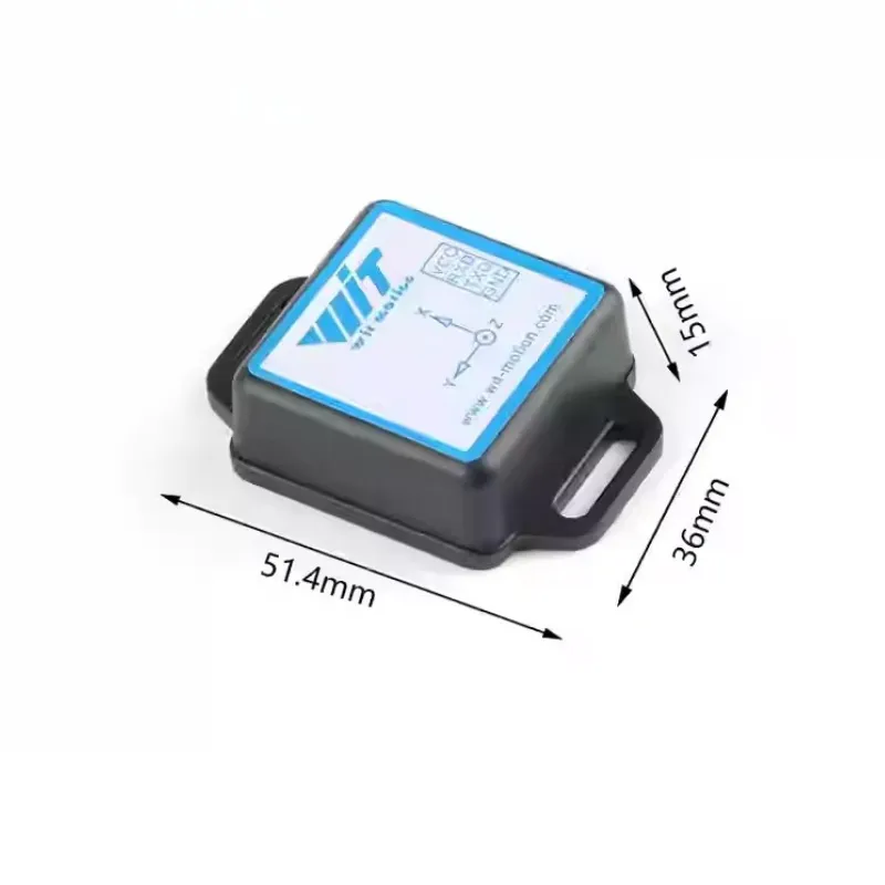
Dimensions: 51.3mm × 36mm × 15mm
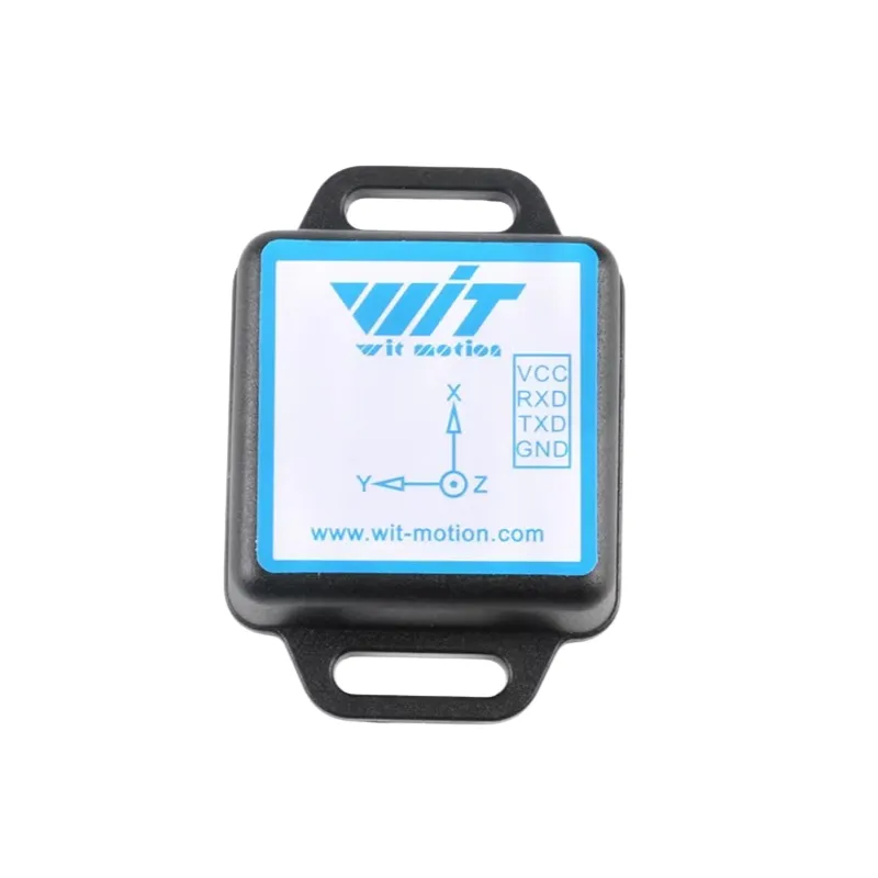
Pinout Description
| Pin | Function |
|---|---|
| VCC | Power supply input (supports 3.3V or 5V) |
| RX | Serial data input (TTL or RS232 level) |
| TX | Serial data output (TTL or RS232 level) |
| GND | Ground |
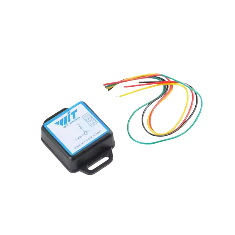
Connection Instructions about WT901C-TTL/RS232 9-Axis MPU6050 Sensor
To connect the module to a computer, a USB-to-TTL serial converter is required.
Connect the pins as follows:
Module VCC → USB-TTL +5V / 3.3V
Module TX → USB-TTL RX
Module RX → USB-TTL TX
Module GND → USB-TTL GND
⚠️ Important: The TX and RX pins must be crossed (TX to RX, RX to TX).
Once connected, plug the USB-TTL adapter into the computer and use serial communication software to read data from the sensor.
Wiring & Usage Guide – WT901C-TTL/RS232 9-Axis MPU6050 Sensor
1. Wiring Instructions
To connect the WT901C-TTL/232 module to a computer, you’ll need a USB to TTL serial adapter (with CH340 or CP210x chip). The correct wiring method is as follows:
Module VCC → USB-TTL +5V/3.3V
Module GND → USB-TTL GND
Module TX → USB-TTL RX (cross-connected)
Module RX → USB-TTL TX
Once properly connected, plug the USB into your computer.
2. Driver Installation & Serial Port Connection
Install the appropriate driver (CH340 or CP210x) for your USB-TTL module. After installation, the COM port number can be found in the Device Manager.
Launch the MiniIMU.exe software (located in the “PC Software” folder of the product package).
Select the correct COM port
Set baud rate to 115200
Click ‘Open’ to start receiving data
Sensor Calibration (Required Before First Use)
To ensure accurate readings, calibration must be done before using the module:
1. Z-Axis Zeroing
This sets the Z-axis angle to 0° in its current position.
Steps:
Keep the module stationary
In the PC software, open the configuration panel
Click the ‘Z-Axis Zero’ button
The Z-axis angle will reset to 0°
Note: The Z-axis will automatically zero itself upon power-up, but manual zeroing is useful if the Z-axis drifts.
2. Accelerometer Calibration
This removes zero-bias errors from the accelerometer for better accuracy.
Steps:
Place the module flat and still
Click the ‘Acc Cal’ (Accelerometer Calibration) button
After 1–2 seconds, X/Y/Z acceleration values should stabilize around 0.01, and X/Y angles should be near 0°
Note: The Z-axis will show about 1g due to gravity when level.
Changing Baud Rate
The module supports multiple baud rates (default: 115200bps). To change:
Ensure the module is connected
Open the configuration panel
Select the desired baud rate from the dropdown menu
⚠️ After changing, you must also select the new baud rate in the PC software, or no data will be received.
Examples:
115200 bps → Update rate: 100Hz
9600 bps → Update rate: 20Hz
Data Logging
The WT901C module does not include internal storage, but data can be logged using the PC software.
How to record:
Click the “Record” button in the software to begin
Click “Stop” to end recording and save the data file
Reviews
There are no reviews yet.