

Key Features
- Dual Encoders – Ensures absolute single-turn position retention, preventing position loss during power failure.
- Integrated Motor and Driver – Compact design with high integration.
- Visual Debugging Support – Allows firmware upgrades and debugging via PC interface.
- CAN Bus Communication – Provides real-time feedback on speed, position, torque, and temperature.
- Dual Temperature Protection – Prevents overheating and enhances operational safety.
- Trapezoidal Acceleration/Deceleration – Enables smooth and precise motion control in position mode.
Extracted Table Content
| Category | Parameter | Value |
| Motor Parameters | Rated Voltage | 24V |
| Rated Current | 2.5A | |
| Peak Current | 7.5A | |
| Rated Torque | 3NM | |
| Peak Torque | 7NM | |
| Rated Speed | 120rpm | |
| No-load Maximum Speed | 200rpm | |
| Motor Characteristics | Reduction Ratio | 10:01 |
| Pole Pairs | 7 | |
| Phase Inductance | 340uH | |
| Phase Resistance | 650mΩ | |
| Structure & Weight | Outer Diameter | 56mm |
| Height | 46mm | |
| Motor Weight | Approx. 300g | |
| Encoder | Encoder Resolution | 14-bit |
| Encoder Channels | 2 | |
| Encoder Type | Magnetic (Single-turn) | |
| Communication | Control Interface | CAN@1Mbps |
| Tuning Interface | UART@921600bps | |
| Control Modes | MIT Mode | |
| Speed Mode | ||
| Position Mode | ||
| Protection & Safety | Drive Overheat Protection | 120°C, Exits “Performance Mode” if exceeded |
| Motor Overheat Protection | Suggested limit: 100°C, Exits “Performance Mode” if exceeded | |
| Overvoltage Protection | Suggested limit: 32V, Exits “Performance Mode” if exceeded | |
| Communication Timeout | If no command received within set period, exits “Performance Mode” | |
| Overcurrent Protection | Suggested limit: 9.8A, Exits “Performance Mode” if exceeded | |
| Undervoltage Protection | If no lower limit is set, suggested minimum voltage: 15V |
Product Package Contents
- Motor (with built-in driver) ×1
- Power and CAN communication cable (XT30(2+2)-F plug) ×1
- Debugging serial signal cable (GH1.25 3-pin) ×1
Interface and Wiring Description
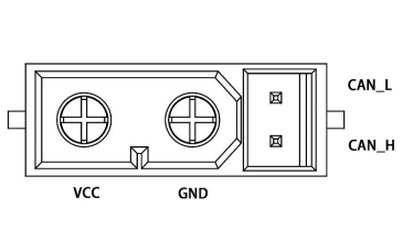
Power Interface-1 (with CAN Communication Terminal)
Pin Labels: VCC, GND, CAN_L, CAN_H
Description:
- Connect the power cable using the XT30(2+2)-F connector to supply power to the motor. The rated voltage is 24V.
- Use the CAN communication terminals to connect to an external control device, allowing the motor to receive CAN control commands and provide feedback on its status.
- The device includes two power interfaces, either of which can be used independently or in series for multiple motors, facilitating wiring.
Power Interface-2 (with CAN Communication Terminal)
Pin Labels: VCC, GND, CAN_L, CAN_H
Description:
- This interface functions the same as Power Interface-1 and can be used as a backup or for multiple motor connections.
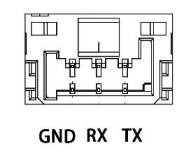
Debug Serial Port-3
Pin Labels: GND, RX, TX
Description:
- Uses a GH1.25 connector (3-pin) and connects via a USB-to-CAN debugging tool (or a standard USB-to-serial module) to a PC.
- Supports motor parameter configuration and firmware upgrades via the Dabotech debugging assistant.
Motor Dimensions and Installation
Please refer to the motor mounting hole dimensions and positions to install the motor onto the corresponding equipment.


Indicator Light Status
- Green Light (Steady On): Normal working state.
- Red Light (Steady On): Fault (e.g., over-voltage, under-voltage, overcurrent).
- Red Light (Flashing): Errors such as MOS over-temperature, communication loss, or overload.
Operating Modes
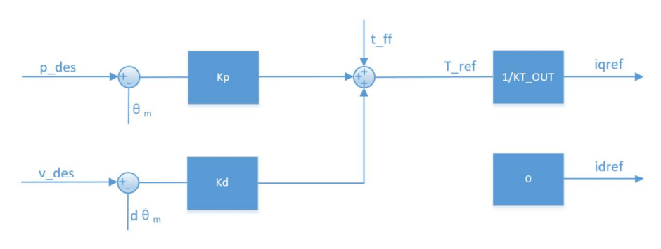
MIT Mode
- Compatible with original MIT control mode.
- Allows flexible settings for position, velocity, and torque control.
- Supports various control behaviors:
- kp=0, kd≠0, v_des → Constant speed rotation.
- kp=0, kd=0, t_ff → Torque-based control.
- Caution: Setting kd=0 in position control may cause instability.
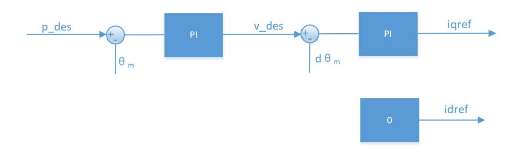
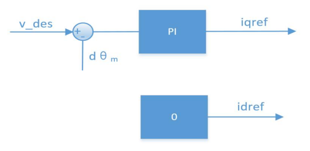
Position-Velocity Mode
- Implements a three-loop cascade control:
- Outer loop: Position control (p_des)
- Middle loop: Speed control (v_des)
- Inner loop: Current control (torque)
- Supports trapezoidal acceleration/deceleration for smooth motion.
- Requires a nonzero positive damping factor.
Velocity Mode
- Maintains a stable speed based on v_des (rad/s).
- Recommended damping factor: 2.0–10.0 for optimal response time.
CAN Communication and Control
- 1Mbps Standard CAN Frame Format
- Feedback Frame Format: Encodes position, speed, and torque using linear mapping.
- Error Codes:
- 8: Over-voltage
- 9: Under-voltage
- A: Overcurrent
- B: MOS over-temperature
- C: Motor coil over-temperature
- D: Communication loss
- E: Overload
Control Frames
- MIT Mode: Uses 8-byte CAN frames with Position, Velocity, Kp, Kd, and Torque data.
- Position-Velocity Mode: CAN ID: 0x100 + ID, Parameters: p_des, v_des.
- Velocity Mode: CAN ID: 0x200 + ID, Parameter: v_des.
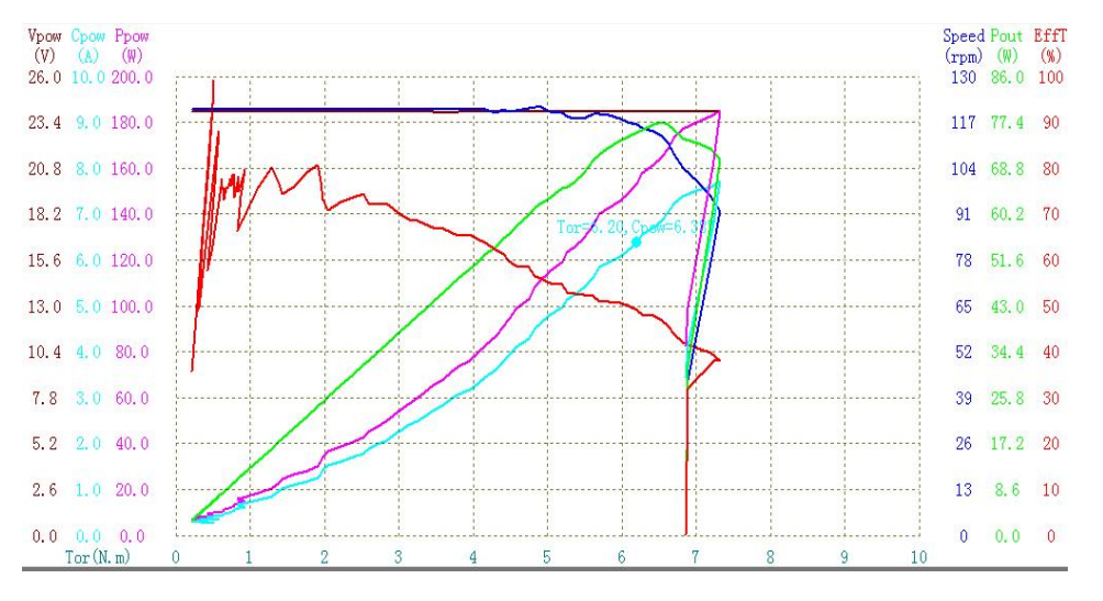
Motor Parameters
Fixed speed: 120 rpm Performance curve measured at room temperature (25°C):
Why Choose DM-J4310-2EC Joint Motor?
- High Precision – Dual encoders ensure accurate position feedback.
- Compact and Lightweight – Integrated motor and driver save space.
- Advanced Control Modes – Supports MIT, Position-Velocity, and Velocity Modes.
- CAN Bus Communication – Enables real-time multi-motor coordination.
- Built-in Protection – Includes over-voltage, under-voltage, overcurrent, and over-temperature protection.
- Easy Debugging – Supports PC-based debugging via USB-to-CAN adapter.
How to Use DM-J4310-2EC in a Robot Arm
- Power Connection
- Connect a 24V power source using an XT30(2+2)-F plug.
- Ensure a stable power supply to avoid voltage errors.
- CAN Communication Setup
- Connect the CAN bus to the master controller.
- Use 1Mbps CAN communication for real-time control.
- Mounting the Motor
- Follow the mounting hole dimensions for secure installation.
- Ensure proper mechanical alignment with robot arm joints.
- Programming and Control
- Select the appropriate control mode (MIT, Position-Velocity, or Velocity).
- Use Damiao Technology Debugging Assistant for parameter tuning.
- Testing and Calibration
- Run initial position and velocity tests to fine-tune PID settings.
- Monitor torque and temperature feedback to prevent overheating.
- Error Handling and Debugging
- Use indicator lights to diagnose faults.
- Check and address error codes (e.g., over-voltage, communication loss).
By integrating the DM-J4310-2ECV1.1 into a robot arm, you achieve high precision, smooth motion control, and real-time feedback, ensuring a reliable and efficient robotic system.