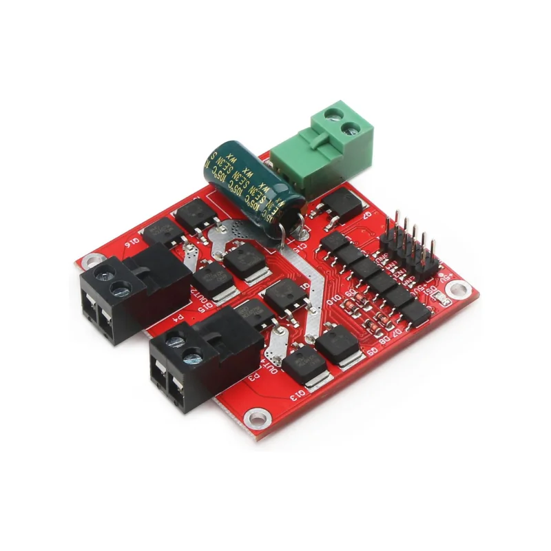
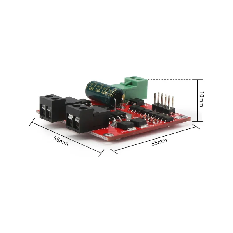
Dual H-Bridge Motor Driver: Capable of driving two DC motors simultaneously with a single-channel maximum current of 7A. Features a wide voltage range of 6.5V to 27V and optocoupler-isolated input signals. Includes isolation and undervoltage protection, designed in compliance with EMC standards, with static discharge circuits ensuring stability and reliability for industrial applications.
Signal Logic
Note: 0 represents low level, 1 represents high level, x represents any level, and when floating, it is considered high level.
| IN1 | IN2 | ENA1 | OUT1, OUT2 Output |
| 0 | 0 | x | Brake |
| 1 | 1 | x | Coast |
| 1 | 0 | PWM | Forward Speed Control |
| 0 | 1 | PWM | Reverse Speed Control |
| 1 | 0 | 1 | Full-Speed Forward |
| 0 | 1 | 1 | Full-Speed Reverse |
| IN3 | IN4 | ENA2 | OUT3, OUT4 Output |
| 0 | 0 | x | Brake |
| 1 | 1 | x | Coast |
| 1 | 0 | PWM | Forward Speed Control |
| 0 | 1 | PWM | Reverse Speed Control |
| 1 | 0 | 1 | Full-Speed Forward |
| 0 | 1 | 1 | Full-Speed Reverse |
Precautions
- Power Connection: Ensure the driver power supply is not connected in reverse. It is recommended to connect a 15A fuse at the power input. The input voltage should be within 6.5V~27V. Overvoltage may damage the driver module upon powering on.
- Power Supply Requirements: The power supply’s rated output current should be at least twice the motor’s rated current to prevent voltage drops during motor startup. Insufficient current may cause the power supply voltage to fall below the driver’s input voltage requirements, triggering undervoltage protection and halting the motor.
- Motor Interface: Avoid short-circuiting the motor interface, as this may damage the driver module. A 10A fuse is recommended at the motor interface.
- Direction Switching: Allow at least 0.1 seconds of braking before reversing the motor’s direction. Do not reverse while the motor is still running, as this may damage the driver.
- Power-Off Precautions: When the driver module is powered off, do not allow the motor to rotate at high speed directly or indirectly, as the back electromotive force generated by the motor may damage the driver. If high-speed motor operation during driver power-off is required, it is recommended to connect a relay (NO and COM terminals in series) at the motor interface. The relay coil should share the same power source as the driver. This setup will disconnect the motor from the driver when the power is off.
- Environmental Protection: Protect the driver from moisture. Avoid short circuits on the driver’s components, and do not touch component pins or pads on the board with your hands.
Reviews
There are no reviews yet.