
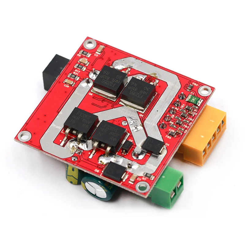
The Motor Driver features an industrial-grade design, ensuring stability and reliability. It includes anti-static circuitry, transient suppression protection, undervoltage protection, ESD protection for interfaces, and overvoltage protection.
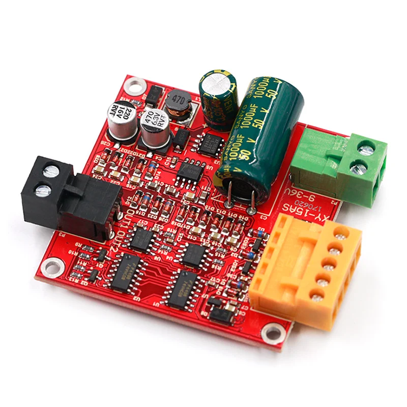
Supports a wide voltage range of 9-36V with continuous load current ratings: 12A (no heat sink), 15A (with basic heat dissipation), and 20A (with a large, robust heat sink).
Adopts a logic similar to the L298 driver, enabling three-wire control (PWM, IN1, IN2) for speed regulation, forward/reverse rotation, and braking.
Supports full PWM functionality and allows direct forward/reverse control via buttons. PWM range: 0.1% to 100.0%.
Provides a 5V power supply for controllers like microcontrollers, with 5V output overcurrent protection and input signal overvoltage protection.
Note: 0 represents low level, 1 represents high level, and x represents any level. If left floating, it defaults to low level.
Pin Details:
- COM: Signal ground.
- 5VO: 5V output for controllers like microcontrollers.
- PWM: External signal input; connect to 5VO for button control mode.
- IN1/IN2: Motor control signals for rotation and braking.
| IN1 | IN2 | PWM | OUT1, OUT2 Output |
| 0 | 0 | X | Brake |
| 1 | 1 | X | High Impedance |
| 1 | 0 | 1 | Full Speed Forward |
| 0 | 1 | 1 | Full Speed Reverse |
| 1 | 0 | PWM | Forward with PWM |
| 0 | 1 | PWM | Reverse with PWM |
Precautions
- The power supply voltage for the driver should be between 6-36V. Exceeding this range may damage the driver when powered on, and voltage too low with high load current may also burn the driver. It is recommended to connect a 20A fuse in series at the power supply.
- When switching between forward and reverse rotation, it is advised to brake for at least 0.1 seconds before reversing, otherwise, the driver may be damaged.
- Since control signal lines are delicate, during use, any control signal line (orange terminal) must not come into contact with the power or motor interface wiring, as this could likely burn out the driver and make it difficult to repair.
- When the driver is powered off, do not rapidly rotate the motor, as the electromotive force generated by the motor may damage the driver. If the application requires rapid motor rotation when the driver is powered off, it is recommended to connect a relay in series at the motor interface. The relay coil should share the power supply with the driver. This will disconnect the motor from the driver when power is lost.
- Ensure the driver is connected to the motor before powering on. Otherwise, the fuse or driver may burn out.
- The motor interface must not short-circuit, as this could burn out the fuse or driver.
- Prevent the driver from getting wet, avoid short-circuiting the components on the driver board, and do not touch the pins or solder pads on the board components with your hands.
- Please carefully read the product description before use. If the module is damaged due to incorrect usage or unauthorized component replacement, returns or exchanges will not be accepted.
Reviews
There are no reviews yet.