
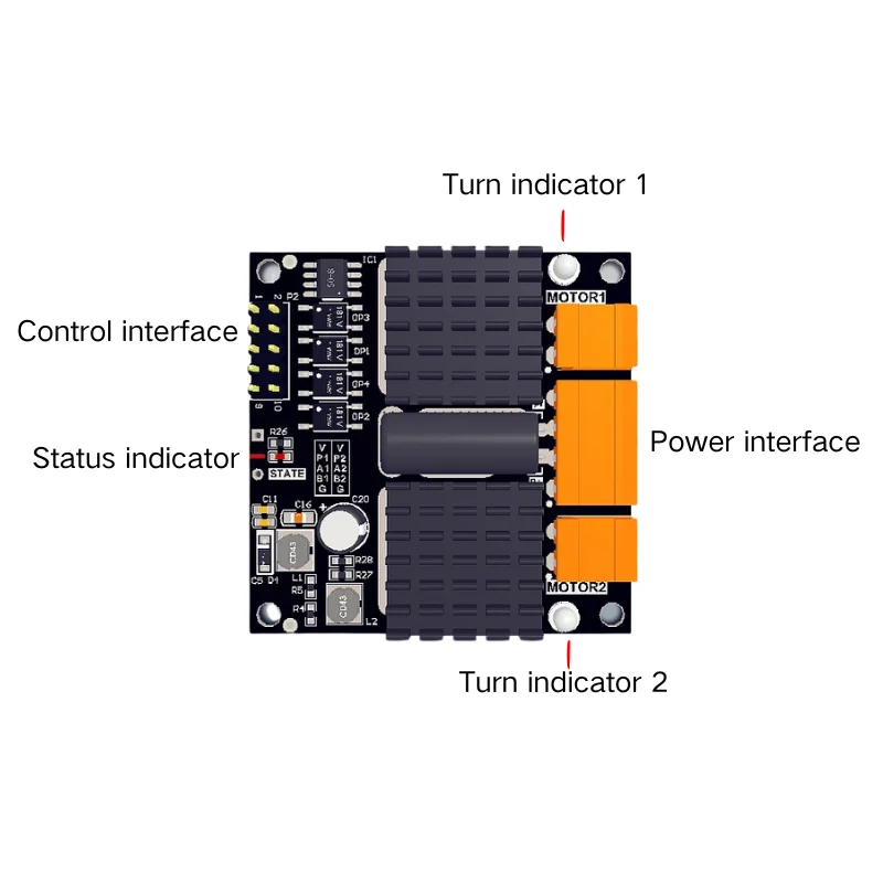
The dual-channel DC brushed motor driver is specifically designed for driving low-voltage DC motors. It uses high-performance MOSFETs in an H-bridge configuration, with each channel capable of continuously outputting 12A of current, driving DC motors with up to 300W of power. The driver’s internal circuitry is highly optimized for timing, allowing the PWM input to have a minimum pulse width as low as 3µs, ensuring dynamic PWM adjustment and improving motor control quality. The onboard protection circuitry reduces the likelihood of driver damage under abnormal operating conditions, with the protection status indicated in real-time via an LED. Fully isolated inputs enhance the safety of the main MCU circuitry and significantly improve the system’s electromagnetic compatibility.
Working parameters
| Parameter | Condition | Min Value | Typical Value | Max Value | Unit |
| Power Supply Voltage VP | 6.5 | 28 | V | ||
| Overvoltage Protection | 28.5 | V | |||
| Undervoltage Protection | 6.3 | V | |||
| Power Supply Current IP | Dual-terminal wiring | 24 | A | ||
| Continuous Output Current Imc | VP=24V, resistive load | 12 | A | ||
| Peak Output Current (100ms) Imp | VP=24V, t = 100ms | 70 | A | ||
| Peak Output Current (10µs) Imp | VP=24V, t = 10µs | 200 | A | ||
| Logic Input Voltage Vin | Same as logic signal amplitude | 3 | 5.5 | V | |
| Logic Input Current Iin | VCC=5V | 15 | 16 | mA | |
| PWM Input Frequency | 18 | 60 | kHz | ||
| PWM Minimum Pulse Width | Positive and negative pulse | 2 | µs | ||
| Overheat Protection | Sensor location | 85 | 95 | °C | |
| Operating Temperature | -25 | 85 | °C |
Note:
- Unless otherwise specified, all tests for this driver are conducted at 20°C in an open environment.
- Dual-terminal wiring refers to connecting two power wires each to the P+ and P- terminals (due to terminal capacity limitations).
- For PWM input frequency, it is recommended to use a value higher than 10kHz. Frequencies below this may result in noticeable current noise. For silent applications, a frequency setting of around 17–18kHz is ideal.
Operation logic
| Signal Input | Power Output | ||||
| INAx | INBx | PWMx | Mx_A | Mx_B | Motor Status |
| L | L | X | L | L | Braking |
| L | H | PWM | PWM | L | Forward Rotation |
| H | L | PWM | L | PWM | Reverse Rotation |
| H | H | X | Z | Z | Coasting |
| The driver has triggered undervoltage or overheating protection. | Z | Z | Coasting | ||
Note:
- In INAx, INBx, PWMx, Mx A, and Mx B, x represents the channel number, which can be either 1 or 2.
- H represents a high level, L represents a low level, X indicates the signal is irrelevant, and Z represents a high-impedance state.
- During large energy forward-reverse switching, braking should be applied for at least 100ms before switching to avoid potential damage to the driver.
Note: When the input signal is floating, it defaults to a high level.
Indicator light description
| Indicator Light | State Description | ||
| Status | State Indicator | Steady On | Normal operation |
| Fast Flashing | Power over-voltage, output disabled | ||
| Slow Flashing | Power under-voltage, output disabled | ||
| Double Flashing | Driver overheating, output disabled | ||
| LM1 | Motor Channel 1 Direction Indicator Green (Forward), Red (Reverse) | ||
| LM2 | Motor Channel 2 Direction Indicator Green (Forward), Red (Reverse) | ||
Feature
- Continuous Output Current: 12.8A
- Operating Voltage Range: 5.6~33V
- Minimum Pulse Width: 0.5µs
- Power Supply Efficiency: 99.6%
- Full Duty Cycle Output Voltage: 23.9V
- Channel Output Power: 380W
- Status Indicator: Power-on high brightness for 0.1s, then steady on
- Dimensions: 50mm x 50mm x 12.5mm
Learn
Typical Applications
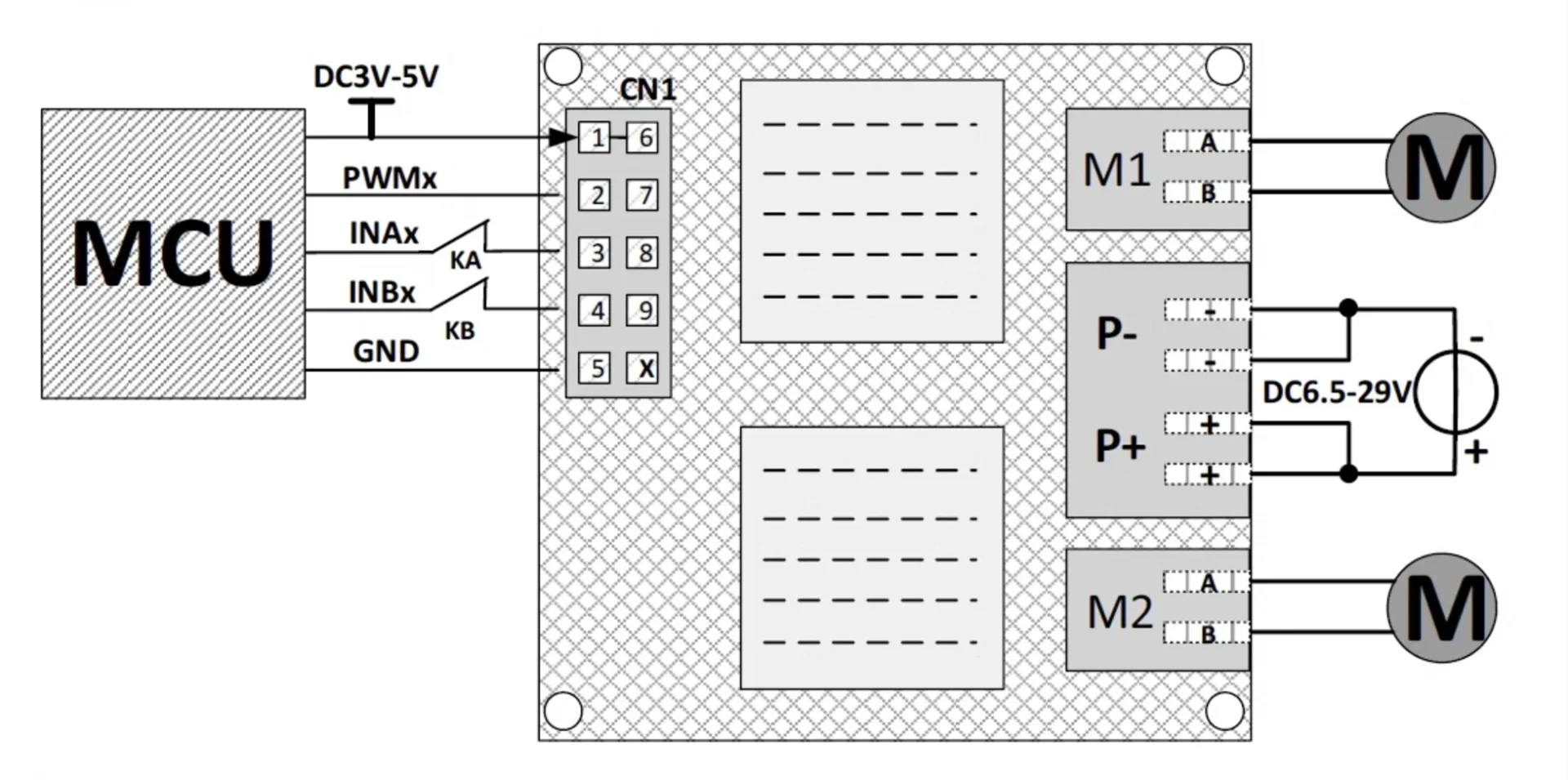
MCU Control the motor operation and add limit switch function (KA, KB are limit normally closed contacts)
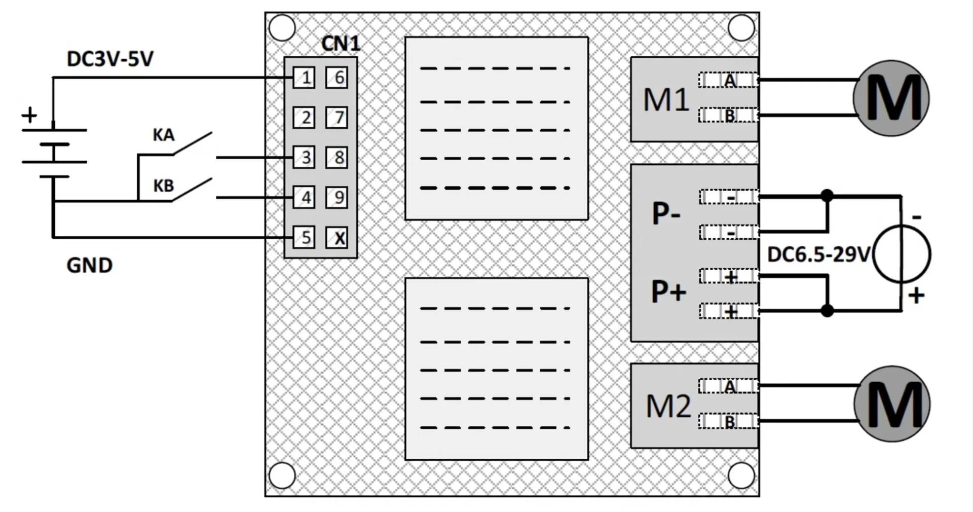
The buttons (KA, KB) control the motor forward and reverse rotation without the need for MCU involvement
| CN1 Pin | Definition | Description |
| 1 | VCC | Isolated positive power input, supports 3.3V and 5V power supplies. |
| 2 | PWM1 | Channel M1 PWM signal input, high-speed isolation, supports up to 50MHz. |
| 3 | INA1 | Channel M1 logic control input A. |
| 4 | INB1 | Channel M1 logic control input B. |
| 5 | GND | Isolated ground input for the power supply. |
| 6 | VCC | Isolated positive power input, supports 3.3V and 5V power supplies. |
| 7 | PWM2 | Channel M2 PWM signal input, high-speed isolation, supports up to 50MHz. |
| 8 | INA2 | Channel M2 logic control input A. |
| 9 | INB2 | Channel M2 logic control input B. |
| X | GND | Isolated ground input for the power supply. |
Notes:
- Input signals default to high level when floating.
- Control input terminal CN1 has a 2.54mm pitch 2×5 dual-row pin header.
Reviews
There are no reviews yet.