
The TB6612FNG motor driver can control up to two DC motors at a constant current of 1.2A (3.2A peak). Two input signals (IN1 and IN2) allow the motor to operate in one of four modes: Clockwise (CW), Counterclockwise (CCW), short-brake, and stop. The motor outputs (A and B) can be controlled separately, and the speed of each motor is regulated using a PWM input signal with a frequency of up to 100kHz. To take the motor out of standby mode, the STBY pin should be pulled high.
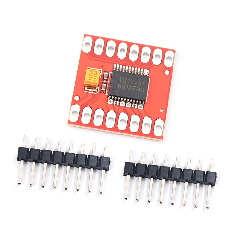
The logic supply voltage (VCC) can range from 2.7 to 5.5V DC, while the motor supply voltage (VM) is capped at a maximum of 12VDC. The output current is rated up to 1.2A per channel (or up to 32A for a short, single pulse). The board comes with all components installed as shown, including decoupling capacitors on both supply lines. All pins of the TIB6612FNG are broken out to two 0.1″ pitch headers, arranged with input pins on one side and output pins on the other.
Features:
Power supply voltage: VM = 12V max, VCC = 2.7-5.5V
Output current: Tout = 1.2A (average) / 3.2A (peak)
Standby control to save power
CW/CCW/short brake/stop motor control modes
Built-in thermal shutdown and low voltage detection circuits
All pins of the TB6612FNG broken out to 0.1″ spaced pins
Filtering capacitors on both supply lines
Video
Learn
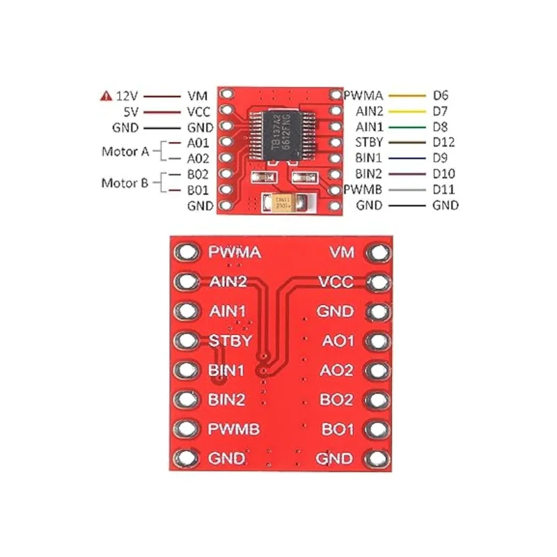
Pin Connections and Control
- STBY Pin
- Connect to the microcontroller’s IO pin.
- LOW (0): All motors stop.
- HIGH (1): Enables motor control through AIN1, AIN2, BIN1, and BIN2 pins.
- VM Pin
- Connect to a power supply of less than 12V (for powering the motors).
- VCC Pin
- Connect to a 5V power supply (for logic control).
- GND Pin
- Common ground for the circuit.
Motor 1 Control (PWMA)
- AIN1 and AIN2 Pins control the direction of Motor 1:
- AIN1 = 0, AIN2 = 0: Stop
- AIN1 = 1, AIN2 = 0: Forward
- AIN1 = 0, AIN2 = 1: Reverse
- PWMA Pin:
- Connect to the PWM signal from the microcontroller to control the speed of Motor 1.
- A01 and A02 Pins:
- Connect to the two terminals of Motor 1.
Motor 2 Control (PWMB)
- BIN1 and BIN2 Pins control the direction of Motor 2:
- BIN1 = 0, BIN2 = 0: Stop
- BIN1 = 1, BIN2 = 0: Forward
- BIN1 = 0, BIN2 = 1: Reverse
- PWMB Pin:
- Connect to the PWM signal from the microcontroller to control the speed of Motor 2.
- B01 and B02 Pins:
- Connect to the two terminals of Motor 2.
Reviews
There are no reviews yet.